


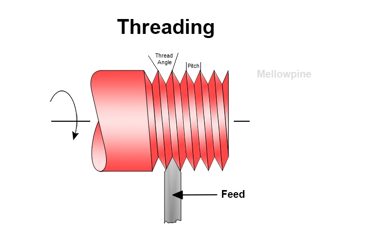
Threading is the process of cutting spiral groves on workpieces to provide a temporary fastening method, and CNC threading provides the ability to cut these threads with high precision and accuracy.
This ensures tight tolerance and better fastening, making it ideal for applications such as lead screw drives, where tight tolerance of threads is of utmost importance.
So what exactly is CNC threading and how is it performed?
CNC threading is the process of using a CNC machine, such as a lathe, to cut internal or external threads on the surface of cylindrical workpieces. CNC lathes use a single-point cutting tool with indexable inserts that match the geometry of the thread. Special threading cycle G-codes are used here.
This article provides a detailed guide on CNC threading by discussing different methods of cutting threads on a CNC lathe.
MellowPine is reader-supported. When you buy through links on my site, I may earn an affiliate commission at no extra cost to you.
What is CNC Threading? Guide
CNC threading is an automated process of cutting precise threads on workpieces.
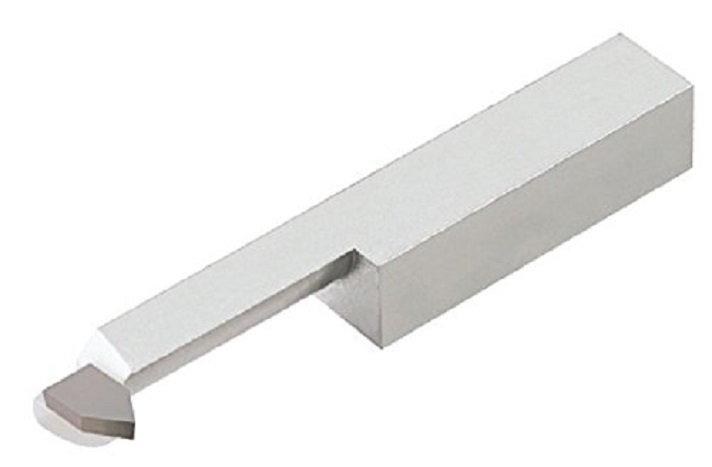
Generally, a CNC lathe is used to perform CNC threading operations, and the single-point cutting tool used for the process has a tool geometry specific for cutting a particular type of thread.
As a result, CNC lathe cutting tools with indexable threading inserts are preferable, as they provide the ability to change the insert according to the required threading operation.
Carbide threading tools are best suited for cutting threads on hard metals, while HSS tools are preferable for softer metals.
CNC threading involves a computer numerical control machine, such as a CNC lathe, which is programmed by a computer system loaded with CNC lathe software, to execute the desired.
The use of a computer-controlled cutting tool enhances the accuracy and productivity of the system, producing threads with tight tolerance.
This process can be used for machining both, internal and external threads, and the advancement of the tool per revolution of the workpiece determines the pitch of the thread being cut.
The high accuracy of CNC threading makes it ideal for cutting threads on transmission drives such as lead screws and ball screws.
Apart from CNC lathes, thread cutting can also be achieved by thread milling and tapping. While tapping uses a solid body tool, you can use an indexable end mill for thread milling.
How to Cut a Thread on a CNC Lathe?
Performing the threading operation on a CNC lathe requires specific codes that guide the cutting tool to remove the material and produce a spiral groove of precise geometry and pitch.
Traditional CNC threading involved writing long codes to describe every step in the threading process, which requires immersive calculations and increases the chances of human error.
Using a Multi Repetitive Cycle (canned cycle), such as the G76 threading cycle, eliminates the need for long codes, thereby minimizing the chances of error.
Performing a threading operation requires some basic information about the thread that is to be cut.
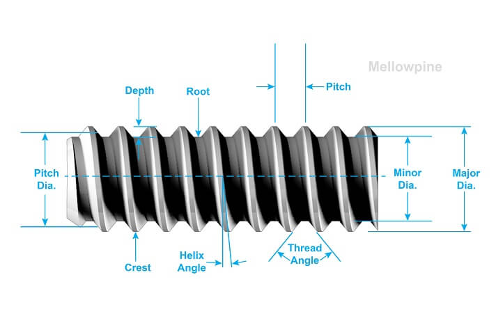
Pitch is the distance between adjacent crests or roots of a thread.
Major diameter is the distance measured between the crests of the thread and is generally referred to as the nominal diameter of the thread.
Thread depth is measured from the crest to the root of the thread.
The depth of the thread can also be calculated by the following equation:
Thread Depth = 0.6134 x Pitch
The minor diameter or “core diameter”, is the smallest diameter that is measured between the roots for external threads, and between the crests for internal threads.
It can be calculated by using the following equation:
Minor Diameter = Major diameter – (2 x Thread Depth)
Generally, a metric thread is denoted by MN x P, where M represents metric units, N is the nominal diameter and P is the pitch of the thread.
After identifying the requirements for the threading operation, there are generally three main cycles used for CNC threading on a lathe.
G32 Threading Cycle
G32 or long-handle threading is a cycle that simplifies the CNC threading process while providing flexibility to cut various types of threads.
This cycle consists of a comparatively longer code than other cycles and generally requires at least 4 blocks of codes to perform a single threading cut.
Furthermore, modifying a G32 threading program requires almost reprogramming the entire code.
However, due to the flexibility in input and ability to control the depth of cut for each thread, this cycle provides the ability to cut special threads such as multi-block threads.
A typical G-code block for a G32 threading cycle consists of the following lines of code:
G32 X(U) Z(V) F(W);
G00 X(A);
Z(O);
Here, X(U) is the x-axis coordinate for threading and is not required when cutting cylindrical threads.
Z(V) is the Z-axis coordinate that specifies the length of threading, and F(W) indicates the feed rate set equal to the pitch of the thread.
The second line of code, i.e., G00 X(A) positions the tool away from the workpiece, followed by Z(O) to bring the tool to work zero position before executing the next cycle.
Let us consider an example of cutting M40 x 2 threads by executing a G32 threading cycle.
To begin the execution, we first need to perform the following calculations:
Depth of thread = 0.6134 x pitch = 1.2 mm
Crest of thread = Nominal diameter – Depth of thread = 38.7 mm
Root of thread = Nominal diameter – (2 x Depth of thread) = 37.6 mm
Based on these calculations, we conclude that the depth of each cut should be equal to 0.65 mm, which means that the total reduction in diameter for each cut will be 1.3 mm.
Therefore,
X coordinate for first cut = 38.7 mm (Crest of thread)
X coordinate for second cut = 38.05 mm
X coordinate for third cut = 37.4 (~Root of the thread)
O1021
N10 M06 T0202 ;
N20 G50 S3000 ;
N30 M03 G97 S1000 ;
N40 M08 ;
N50 G00 X40 Z7 ;
N60 G32 X38.7 Z-50 F2 ;
N70 X38.05 ;
N80 X37.4 ;
N90 G28 U0 W0 ;
N100 M05 M09 M30 ;
In this example, the first line of code, i.e., 01021 indicates the program number to uniquely identify your machining program.
- The next line, N10, is a tool change command to select tool number 2.
- N20 signifies the maximum tool speed of 3000 RPM.
- N30 initiates clockwise spindle rotation with a uniform speed of 1000 RPM.
- N40 turns the coolant flow on.
- N50 performs rapid translation of the cutting tool to the position where X and Z coordinates are 40 and 7 respectively.
- N60 initiates the threading cycle and performs the first cut with the X coordinate set at 38.7 and a feed rate equal to the pitch of the thread.
- N70 executes the second threading cut with the X coordinate set at 38.05.
- N80 executes the third threading cut with the X coordinate set at 37.4, which is roughly equal to the root of the thread.
- N90 brings the cutting tool to the home position or origin point (0,0).
- N100 turns off the spindle, turns off the coolant, and shuts down the main program.
G76 Threading Cycle
G76 is one of the most commonly used threading cycles on CNC lathes.
It consists of a one-line or two-line code that automatically executes the cut repetitively until the desired thread is produced.
The G76 cycle can be used to cut external, internal, and tapered threads.
However, it does not provide the flexibility to cut special threads and is generally used for cutting constant lead single-start threads.
A typical G76 cycle code has the following structure:
G76 X__ Z__ I__ K__ D__ A__ Q__ P__ F__
Where,
X value represents the core or minor diameter of the thread
Z value represents the length of the thread
I value represents the amount of taper on the thread and is only required when performing tapered threading.
K value represents the depth of the thread
D value represents the depth of cut in each threading cycle
A value represents the angle of the threading insert being used
Q value is a special function that represents the thread starting angle and is only required for multi-start threads.
P value determines the infeed method or the thread-cutting pattern
F value is the feed rate, and should always be equal to the pitch of the thread or thread lead for multi-start threads.
Similarly, a 2-block G76 code, generally used in old Fanuc controllers, has the following structure:
G76 P______ Q__ R__
G76 X__ Z__ R__ P__ Q__ F__
Here, in the first line of code:
P value consists of six-digit data where the first pair represents the number of finishing passes (01-99)
The second pair of data under P value represents the angle at which the threading operation breaks off. It is also known as G76 chamfer.
The last pair of data under P value represents the thread angle.
Similarly, Q represents the minimum depth of cut to be maintained throughout the process, and R represents the amount of finishing allowance in the thread.
Second line of Code:
X represents the core diameter or minor diameter of the thread.
Z represents the thread length.
R represents the amount of taper required in the thread.
P represents the depth of thread.
Q represents the first pass or the crest of the thread.
F represents the feed rate, and should always be equal to the pitch of the thread or thread lead for multi-start threads.
Let us consider the same example and G76 threading cycle to cut M40 x 2 threads.
O1022
N10 M06 T0202 ;
N20 G50 S3000 ;
N30 M03 G97 S1000 ;
N40 M08 ;
N50 G00 X40 Z7 ;
N60 G76 X37.6 Z-50 K1.2 D0.65 A60 P2 F2
N90 G28 U0 W0 ;
N100 M05 M09 M30 ;
In this code, only one line, i.e., N60 executes the entire threading process by performing multiple threading cycles with a depth of cut of 0.65mm per cycle until the desired thread is achieved.
This simplifies the process of CNC programming the lathe for thread cutting but restricts the ability to control the cut in each cycle.
Things to Consider For CNC Threading
When performing a CNC threading operation, it is important to understand your requirement and choose the best suitable threading process.
Type of Thread
Understanding the requirement of the type of thread helps you select the appropriate threading cycle.
Although G76 cycle is one of the most compact and easy-to-use cycles, it does not provide the feasibility to cut special threads.
Therefore a G32 or G33 threading cycle is recommended for such threads as it provides greater control over the threading process.
Type of Cutting Tool
The type of cutting tool to be used is also a decisive factor for your thread-cutting operation.
Threading operation is generally considered a combination of cutting and forming.
The cutting tool glides through the workpiece to remove the material while also forming the required shape of the threads.
Therefore, it is important to select the right threading tool for your threads to be cut.
Furthermore, the choice of the cutting tool also depends upon the type of cycle being used.
For example, the G76 threading cycle only supports insert angles of A0, A29, A30, A55, A60, and A80. Hence cannot be used for machining threads when using a special cutting insert.
Infeed Technique
When cutting threads on a CNC machine, the movement that the tool follows when plunging in the workpiece to cut the tread is known as infeed.
Generally, there are three types of infeed movements: Radial infeed, modified flank infeed, and incremental infeed.
Radial Infeed
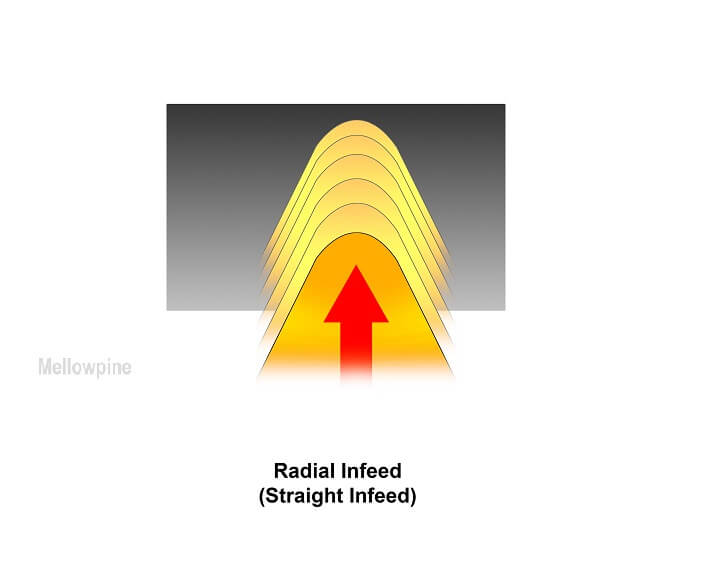
In this type of infeed, the cutter is radially plunged into the workpiece.
This means that the cutter enters the workpiece surface at a 0-degree angle and keeps moving in gradually until it attains the desired depth.
Although it is the most simple infeed method to implement, it increases the cutting force required to remove the material and enhances tool wear.
Apart from that, the threads produced by this technique have minimal helix angle, making them stiff to engage during fastening.
Modified Flank Infeed

Modified flank infeed involves inserting the cutting tool into the workpiece at an angle.
This speeds the cutting force along the entire flank of the cutting tool, thereby eliminating stress concentration and enhancing tool life.
Apart from that, modified flank infeed improves chip formation and minimized heat generation during the cutting process.
Therefore, modified flank infeed is one of the most commonly used cutting techniques for CNC threading operations.
Incremental Infeed
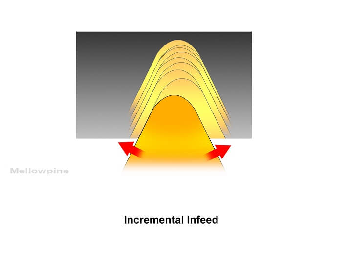
Incremental infeed involves oscillatory movement of the cutting tool from side to side.
In this technique, the cutting tool undergoes rapid to and fro movement to cut the required thread while feeding the cutting tool at the desired angle.
As a result, this process increases the vibration of the cutting tool and results in chatter along the threaded surface.
However, it is the best-suited infeed technique for cutting threads with large pitch.
Final Thoughts
CNC threading enables to produce precise threads with tight tolerance, leading to a perfect fit during fastening.
Although there are various CNC tools to cut threads, CNC lathes are the most commonly used machine for threading operations.
However, you can also perform CNC threading operations by tapping and thread milling.
Depending upon your requirement, you can use different threading cycles such as G32, G76, G92, etc., to cut threads of the desired specification.
Frequently Asked Questions (FAQ)
What is tapping?
Tapping is a process of cutting internal threads on a workpiece by using a cylindrical tool of required thread geometry.
What is thread milling?
Thread milling is the process of cutting threads on a milling machine by using specific thread milling tools. Unlike tapping, it can be used to produce internal and external threads of various sizes.
Can we use CNC threading to cut Acme threads?
Yes, CNC threading can be used to produce almost any type of threads, provided you use the appropriate threading cycle with required parameters.