


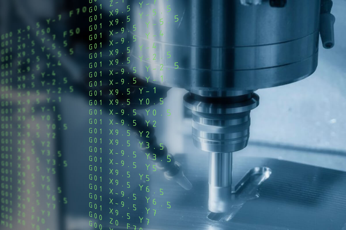
G-code is a series of preparatory commands used to control CNC machines. It can be programmed manually or using software programs.
G-codes Used on CNC Mills
The following is a list of G-codes used to program CNC mills and machining centers.
| G code | Function |
|---|---|
| G00 | Rapid positioning |
| G01 | Linear interpolation |
| G02 | Clockwise circular interpolation |
| G03 | Anticlockwise circular interpolation |
| G04 | Dwell or Pause (used in a separate block) |
| G09 | Exact stop (for stopping the axes) |
| G10 | Setting programmable input data |
| G11 | Canceling data setting mode |
| G15 | Canceling polar coordinate command |
| G16 | Interprets polar coordinate command |
| G17 | Commands designated to the XY plane |
| G18 | Commands designated to the ZX plane |
| G19 | Commands designated to the YZ plane |
| G20 | Imperial/English units of input |
| G21 | Metric units of input |
| G22 | Turns on stored stroke check |
| G23 | Turns off the stored stroke check |
| G25 | Turns on spindle speed fluctuation detection |
| G26 | Turns off spindle speed fluctuation detection |
| G27 | Checks the machine’s zero position |
| G28 | Machine returns to its zero position (point A) |
| G29 | The machine returns to point A, then to the location specified on G29 |
| G30 | The machine returns to point A, then to a zero position (point B) |
| G31 | Skip function |
| G40 | Cancels the cutter radius compensation |
| G41 | Compensates the left cutter radius |
| G42 | Compensates the right cutter radius |
| G43 | Compensates for a positive tool length |
| G44 | Compensates for a negative tool length |
| G45 | Position compensation – single increase |
| G46 | Position compensation – single decrease |
| G47 | Position compensation – double increase |
| G48 | Position compensation – double decrease |
| G49 | Cancels the tool length offset |
| G50 | Cancels the scaling function |
| G51 | Scaling function |
| G52 | Switches to a local/child zero position |
| G53 | Switches to the machine’s default zero position |
| G54 | Work coordinate offset I |
| G55 | Work coordinate offset 2 |
| G56 | Work coordinate offset 3 |
| G57 | Work coordinate offset 4 |
| G58 | Work coordinate offset 5 |
| G59 | Work coordinate offset 6 |
| G60 | Positions the machine in a single direction |
| G61 | Stops the machine |
| G62 | Modal automatic corner override |
| G63 | Tapping mode |
| G64 | Cutting mode |
| G65 | Calling custom macro commands (one time) |
| G66 | Calling custom macro commands (on every machine movement) |
| G67 | Cancels custom macro call commands |
| G68 | Rotates the coordinate system at an angle |
| G69 | Cancels the coordinate system rotation |
| G73 | Peck and canned drilling cycles |
| G74 | Left-hand rigid tapping or threading cycle |
| G76 | Fine boring cycle |
| G80 | Cancels active canned cycles |
| G81 | Drilling cycle |
| G82 | Dwell drilling cycle |
| G83 | Deep hole peck-drilling cycle |
| G84 | Right-hand rigid tapping or threading cycle |
| G85 | Reaming cycle |
| G86 | Boring cycle |
| G87 | Back boring cycle |
| G88 | Boring and dwelling cycle |
| G89 | Back boring and dwelling cycle |
| G90 | Absolute dimensioning mode |
| G91 | Incremental dimensioning mode |
| G92 | Setting an offset on the coordinate system |
| G98 | The tool returns to the initial position |
| G99 | The tool returns to the R plane in a fixed cycle |
M-codes Used on CNC Mills
In a typical CNC program, G-codes and M-codes are used in combination. M-code controls the machine functions like the spindle on/off, tool change, coolant on/off, etc.
Following are some of the M-codes associated with programming CNC mills.
| M-Code | Function |
|---|---|
| M00 | Compulsory program stop |
| M01 | Optional program stop |
| M02 | End of the program (can end with reset, but no rewind) |
| M03 | Spindle rotation (normal) |
| M04 | Spindle rotation (reverse) |
| M05 | Spindle stop |
| M06 | Automatic tool change |
| M07 | Turns on the coolant mist |
| M08 | Coolant ON (turns on the coolant pump) |
| M09 | Coolant OFF (turns off the coolant pump) |
| M19 | Spindle orientation along 0 to 360 degrees |
| M30 | The program ends with reset and rewind |
| M48 | Turning off the feed rate override cancel |
| M49 | Turning on the feed rate override cancel |
| M60 | Automatic pallet change |
| M78 | B-axis clamp |
| M79 | B axis unclamp |
| M98 | Subprogram call |
| M99 | Subprogram end |
G-code Used on CNC Lathes
Since CNC lathes have a unique machining setup, they are programmed using certain lathe-specific codes.
In a CNC program, these lathe-specific G-codes are used with other general G-codes to complete the program.
G32 is an example of one such lathe-specific G-code that is used to execute a CNC threading cycle.
It takes in the input from the CNC operator and removes material to produce different types of threads like circular threads, acme threads, etc.
Following is a list of G-codes used to program CNC Lathes.
| G-code | Function |
|---|---|
| G00 | Rapid positioning |
| G01 | Linear interpolation |
| G02 | Clockwise circular interpolation |
| G03 | Anticlockwise circular interpolation |
| G04 | Dwell or Pause (used in a separate block) |
| G09 | Exact stop (for stopping the axes) |
| G10 | Setting programmable input data |
| G11 | Data Setting mode cancel |
| G20 | Imperial/English units of input |
| G21 | Metric units of input |
| G22 | Turns on stored stroke check |
| G23 | Turns off the stored stroke check |
| G25 | Turns on spindle speed fluctuation detection |
| G26 | Turns off spindle speed fluctuation detection |
| G27 | Checks the machine’s zero position |
| G28 | Machine returns to its zero position (point A) |
| G29 | The machine returns to point A, then to the location specified on G29 |
| G30 | The machine returns to point A, then to a zero position (point B) |
| G31 | Skip function |
| G32 | To cut screw threads |
| G35 | Clockwise circular threading cycle |
| G36 | Counterclockwise circular threading cycle |
| G40 | Cancels the cutter radius compensation |
| G41 | Compensates the left cutter radius |
| G42 | Compensates the right cutter radius |
| G50 | Position register, Set spindle speed range |
| G52 | Switches to a local/child zero position |
| G53 | Switches to the machine’s default zero position |
| G54 | Work coordinate offset 1 |
| G55 | Work coordinate offset 2 |
| G56 | Work coordinate offset 3 |
| G57 | Work coordinate offset 4 |
| G58 | Work coordinate offset 5 |
| G59 | Work coordinate offset 6 |
| G61 | Stops the machine |
| G62 | Modal automatic corner override |
| G64 | Cutting mode |
| G65 | Calling custom macro commands (one time) |
| G66 | Calling custom macro commands (on every machine movement) |
| G67 | Cancels custom macro call commands |
| G68 | Rotates all axes to a specific angle |
| G69 | Cancels G68 comand rotation |
| G70 | Finishing cycle |
| G71 | Rough turning cycle along the Z-axis direction |
| G72 | Rough turning cycle along the X-axis direction |
| G73 | Pattern repetition cycle |
| G74 | Drilling cycle |
| G75 | Grooving cycle |
| G76 | Threading cycle |
| G90 | Cutting cycle A (Group type A) |
| G90 | Absolute positioning command (Group type B) |
| G91 | Incremental positioning command (Group type B) |
| G92 | Thread cutting cycle (Group type A) |
| G92 | Registers tool position (Group type B) |
| G94 | Cutting cycle B (Group type A) |
| G94 | Feedrate per minute (Group type B) |
| G95 | Feedrate per revolution (Group type B) |
| G96 | Constant surface speed (CSS) cutting mode |
| G97 | Cancels G96 command |
| G98 | Feedrate per minute (Group type A) |
| G99 | Feedrate per revolution (Group type A) |
M-codes Used on CNC Lathes
| M-Code | Function |
|---|---|
| M00 | Compulsory program stop |
| M01 | Optional program stop |
| M02 | End of the program (can end with reset, but no rewind) |
| M03 | Spindle rotation (normal) |
| M04 | Spindle rotation (reverse) |
| M05 | Spindle stop |
| M07 | Turns on the coolant mist |
| M08 | Coolant ON (turns on the coolant pump) |
| M09 | Coolant OFF (turns off the coolant pump) |
| M10 | Chuck jaw open |
| M11 | Chuck jaw close |
| M12 | Quill moves toward the tailstock |
| M13 | Quill moves out of the tailstock |
| M17 | Forward turret indexing |
| M18 | Reverse turret indexing |
| M19 | Spindle orientation |
| M21 | Tailstock move forward |
| M22 | Tailstock move backward |
| M23 | Gradually pull out of the thread |
| M24 | Turns off thread gradual pull-out |
| M30 | The program ends with reset and rewind |
| M41 | Selects a low-gear transmission |
| M42 | Selects a gear higher than on M41 (if any) |
| M43 | Selects a gear higher than on M42 (if any) |
| M44 | Selects a high-gear transmission |
| M48 | Turning off the feed rate override cancel |
| M49 | Turning on the feed rate override cancel |
| M98 | Subprogram call |
| M99 | Subprogram end |
List of Letter Blocks on G-code
Letters and numbers are the building blocks of a G-code program. So far, I’ve only listed the popular number blocks. Now I’ll introduce the letter blocks.
G and M are the most used letters in a G-code program. This is because the letter G is used to call out the general functions, and M is used to call the miscellaneous/machine functions.
Following are the other letter blocks used in a G-code program.
| Letter | Denotes |
|---|---|
| A | Machine’s A-axis |
| B | Machine’s B-axis |
| C | Machine’s C-axis |
| D | Diameter/radius compensation for tool |
| E | Precise feed rate (used on lathes for threading operations) |
| F | Feed rate |
| H | Cutter length |
| I | Center of an arc along the X-axis Also in G87 as X offset |
| J | Center of an arc along the Y-axis Also in G87 as Y offset |
| K | Center of an arc along the Z-axis Also in G87 as Z offset |
| L | No. of loop repetitions To specify the register that needed to be edited using G10 |
| N | Program line/block number |
| O | Naming the program |
| P | Parameter address for G-codes and M-codes |
| Q | Feed increment in canned cycle |
| R | Radius of arc Retract length in canned cycle |
| S | Spindle speed |
| T | Tool selection |
| U | Associated with A-codes |
| V | Associated with B-codes |
| W | Associated with C-codes |
| X | Machine’s X-axis |
| Y | Machine’s Y-axis |
| Z | Machine’s Z-axis |
List of G-code Commands
| Command | G-codes |
|---|---|
| Non-modal | G04, G09, G10, G11, G27, G28, G29, G30, G31, G37, G45, G46, G47, G48, G50, G51, G52, G53, G60, G60, G70, G71, G72, G73, G74, G75, G76, G92 |
| Motion | G00, G01, G02, G03 |
| Cutting | G32, G35, G36, G90, G92, G94 |
| Feed rate | G93, G94, G95 |
| Polar input | G15, G16 |
| Plane selection | G17, G18, G19 |
| Dimensioning | G90, G91 |
| Stored strokes | G22, G23 |
| Unit input | G20, G21 |
| Cutter radius offset | G40, G41, G42 |
| Tool length offset | G43, G44, G49 |
| Cycles | G73, G74, G76, G80, G81, G82, G83, G84, G85, G86, G87, G88, G89 |
| Return | G98, G99 |
| Canceling scaling | G50 |
| Image mirroring | G68, G69 |
| Coordinate system | G54, G55, G56, G57, G58, G59 |
| Coordinate rotation | G68, GG69 |
| Cutting mode | G61, G62, G63, G64 |
| Macro mode | G66, G67 |
| Constant Surface Speed | G96, G97 |
| Spindle speed fluctuation | G25, G26 |
These G-code commands are used for milling and turning applications, but some of them are job specific.
For example, the polar input, tool length offset, coordinate rotation, return, and plane selection commands are only used for milling jobs.
Whereas in the case of programming lathes, constant surface speed, mirror image, and cutting cycles are some of the lathe-specific commands.
Frequently Asked Questions
What is CNC programming?
CNC programming is the process of automating the machining process of a CNC machine by writing a CNC program using G-code. This task is usually performed by a CNC machinist.
Is learning G-code easy?
Yes, learning G-code is easy if you understand its structure and its building blocks. A G-code program is a command to the CNC machine directing it to perform specific tasks. If you can understand the purpose of each building block, then you can easily learn CNC programming.
How is the G-code program generated?
The G-code programs are generated using CAM (Computer-Aided Manufacturing) software programs. This software analyses geometrical data from design files and generates program code for specific machines to manufacture the part.